
Hydrogen-energy sandpad modeling: new energy sandpad model customization
Hydrogen Sand Table Modelling: Customization of a new energy sand table model for a complete resolution
In the current profound transformation of the energy structure, hydrogen energy is moving from concept to large-scale application as the most potentially clean energy carrier. However, how can investors, the public and trainees visualize the logic of the hydrogen energy industry, which is long, multi-connected and technically abstract? Hydrogen-enabled sandpad modelling. It is not only a microcosm of geospatial space, but also a dynamic evolution platform that “makes, stores, transports, uses” the entire chain. This physical teaching tool, built by specialized new energy sandpad designers, transforms invisible hydrogen molecular flows into visible light currents and mechanical movements, and serves as a central vehicle for the presentation of future energy scenarios.
Conceptual breakdown: mapping from abstract energy to physical logic
The hydrogen-energy sandpad model is customised at the core of the dual reduction of the “hydrogen-energy industry chain” and the “physical space”. It is not just a microcopy of buildings and equipment, but a visual translation of the energy conversion process.
Core constituent elements:
●
All elements of the industrial chain cover: Models follow strictly the logic of the hydrogen energy industry and typically include “hydrogen zones” (e.g. electrolytic hydrogen, by-product hydrogen production), “purification compression areas”, “storage areas” (e.g. high pressure storage tanks, liquid hydrogen tanks, hydrogen pipelines) and “application areas” (e.g. hydrogen stations, hydrogen fuel cell power stations, hydrogen vehicles). Each link is structured according to real industrial processes to ensure logical rigour.
●
Visual simulation of dynamic processes: This is the soul of the hydrogen energy model. As hydrogen itself is colourless and odourless, the model simulates changes in the direction and pressure of hydrogen in transparent pipelines through high-lighted LED lamps (often using blue or green symbols of clean energy). The electrochemical reaction is simulated within the cell by light flashing, the replicating of the conversion journey of "electric-hydro-electric energy" in combination with the acoustic-photo effects of a mechanical structure.
●
The precise expression of the technical route: Models are differentiated in structure for different hydrogen production methods (e.g. alkaline cells, PEM cells) or for hydrogen storage methods (gas, liquid, solid). For example, the LHP will focus on deep cooling equipment and insulation structures, while the wind-photographic hydrogen coupling model will integrate wind generators and photovoltaic models, visualizing the sources of green hydrogen.
Questions and answers: Customized core values
Question one: Are modelling safe because the hydrogen energy project involves safety risks such as high pressure and flammability? Can it really reflect complex chemical reactions?
Answer: Specialized new energy pallet model custom manufacturers strictly follow safety norms, using flame retarding, resistant engineering materials (e.g. ABS, Yakli, metal) to ensure that the model itself is safe. For the “reaction process” of concern to the audience, the model does not actually react chemically, but is restored by “physical simulations + visual effects”. For example, electrolyte hydrogen processes, models demonstrate intuitively the principle of “water molecule separation” through the movement and scintillation of internal LED lamps, coupled with the simulation of water tank fluid drops and hydrogen bubbles (through micro-gas pumps and transparent particles). This simulation avoids real dangers and allows the audience to understand clearly the response mechanisms.
Question two: How do models distinguish between demonstration and demonstration of hydrogen energy technologies with many routes (e.g. grey, blue, green)?
Answer: That's the advantage of custom models. A generic model can only display a general process, while a customized model can precisely lock in a particular technology route. Production plants are distinguished by different colour markings and equipment configurations according to client needs. For example, when displaying “green hydrogen”, the model will focus on the construction of large-scale wind, photovoltaic arrays and cells, and green light will be used to represent green electric input; when displaying “blue hydrogen” or “grey hydrogen”, the corresponding fossil energy hydrogen units and carbon capture (CCUS) equipment model will be constructed. Through this customised visual coding, viewers are able to discern the production pathways and environmental impacts of different hydrogen sources.
Strategic value of customised practices
Customization of the hydrogen chassis model, the value of which is reflected in three dimensions: solicitation, science and teaching.
●
Recruit and display dimensions: It's a "forecasting ground for future energy." At hydrogen energy parks or fairs, a dynamic pallet can visualize the park ' s industrial layout, infrastructure alignment and vision for the future, enhance investor confidence and improve project landing efficiency.
●
Kopwido: It's a “clean energy translator”. For the public, the concept of hydrogen energy is obscure, and models remove cognitive gaps through visual visual language, spread knowledge about hydrogen energy safety and environmental values, and help to create good social acceptance.
●
Teaching dimensions: It is a “real training platform for composite talent”. For vocational colleges and training institutions, the model provides a real equipment recognition and process exercise environment in which participants can master operational logic and emergency disposal processes without entering a real high-pressure plant area, reducing training risks and costs.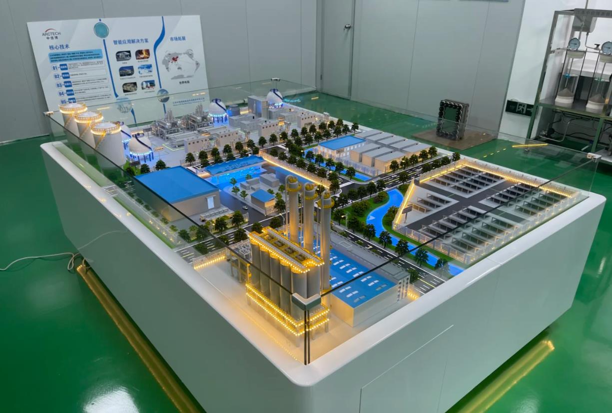
Implementation path: a four-step approach from blueprint to entity
Step 1: Needs diagnosis and programming
The production team needs to communicate in depth with A (e.g., energy enterprises, park management committees, schools) to clarify the core elements of the model presentation (with emphasis on industry-wide chain demonstrations or plant-specific processes), scale, size and functional needs (static presentations, dynamic demonstrations, interactive controls). Collection of the project ' s total plan, process flow chart (PFD/P&ID) and key equipment information.
Step 2: Digital modelling and visual design
Based on the collected drawings, 3D modelling software is used to build the digital prototype. Focus on the design of pipeline paths and light control systems and the planning of light colours and flow logic for different links (production, storage, transport, use). Design interactive interfaces (e.g. touch screen control procedures) to produce impact maps and dynamic demonstration videos to ensure that visual effects are in line with expectations.
Step three: precision manufacturing and system integration
High-precision terrain and building floors are made using CNC fine sculptures, and complex reactor and equipment casings are produced by 3D printing. Transparent Yakli controls are used as conduits and are inserted into LED lamps. Installation of mini-engineers, pumps (for simulated water cycles) and control of main panels, integration of mechanical, electronic, light systems to ensure synergy of work among subsystems.
Step 4: Total assembly debugging and delivery
All components are assembled on the base and connected to the power and signal lines. Joint system-wide debugging to calibrate the synchronization of light flow, mechanical action and speech interpretation to ensure that process processes demonstrate logical clarity and smooth operation. Conduct leakproof electrical and structural stability tests. Operational training and maintenance manuals are provided after on-site installation.
Case in practice: Imaging expression of the future of hydrogen
Case one: "The whole-industry chain demonstration sandpad" at a hydrogen energy estate
The entire view of the model shows the complete closure of the vehicle applications from upstream wind-ray hydrogen and mid-stream liquid hydrogen reserves to downstream hydrogen fuel cells. Through touch screen control, viewers can click on any link and the model will highlight the facility and play the presentation. In particular, a comparative demonstration model of “green hydrogen” and “grey hydrogen” was designed to distinguish between light flows of different colours, visualize the carbon abatement benefits and become the “gown garden treasure” of the park to be used by the marketers.
Case II: “Teaching model for electrolytic hydrogen processes” at a university
In conjunction with the teaching of new energy professions, the plant customises a 1:10 scale model of alkaline electrolytic cells and assistive systems. The model uses a fully transparent shell and the internal electrode plate structure is clear. Through a dynamic demonstration, participants can visualize the electrolyte cycle, the separation of hydrogen gas from oxygen, and simulate the production efficiency at different current density through instrument readings. The model has greatly improved students ' understanding of electrochemical engineering and filled gaps in real-time teaching.
The hydrogen chassis model, which is the “microscopy” of the future energy landscape; it paints the cycling path of hydrogen with a mobile light; and it interprets the logic of green development with sophisticated structures. For institutions committed to the development of the hydrogen energy industry, a well-designed sand table model is not only a demonstration tool, but also a key to a clean energy future.
