Large engine modeling
Large engine modelling is the overall structure, core parts, power transmission systems and operating principles of industrial, engineering-specific large engines (covering diesel engines, gas engines, steam engines, turbine engines, etc.), reduced by a given percentage, integrating sophisticated mechanical recapturing, material simulation, detailed grinding, functional simulations, etc., and creating visualization, decomposable, demonstrationable physical model carriers。Its core value lies in breaking down the limitations of the large engine's “large size, sophisticated structure, closed operation”, transforming abstract power theory, complex mechanical architecture into an observationable, interpretable, interactive physical model, visualizing the core characteristics and operating logic of the large engine, which is widely used in the demonstration of mechanical manufacturing enterprises, engine technology training, practical training in mechanical engineering in institutions, industrial education, model collector collections and exhibition promotion, and is an important visualized bridge linking engine mechanical theory, engineering design and operational practice to help people quickly master the core structure and technical elements of the large engine.。
I. Decomposition of core concepts for large engine modelling
Large engine modeling, distinguished from the replicating of small engine toys or simple stylings, with the core being “precision recoupling, approximation of principles, qualitative reduction”, is a complex and complex integration of mechanical engineering, materials, precision processing, power simulation. Its core concept can be broken down into three key dimensions, each of which is rounded and synergized, ensuring that the model fits the mechanical form of a real large engine while highlighting the core features of the large engine, which is “heavy, well-structured, dynamic and demanding”, taking into account professionalism, practicality and appreciation.
First of all,Proportional design and corporate form reductionThis is the basic premise of modelling.。Proportional selection needs to be combined with engine type, size specification, model use and display space, with core adherence to the "compatibility and precision" principles - - Models for the presentation, desktop displays and collections at a small scale (1:20 to 1:50), focusing on the integrity and portability of the overall structure, highlighting the heavy mechanical quality of large engines Sensor.;Models for hands-on teaching, technology promotion, with a large proportion (1:10-1.15), with a focus on retrofitting the details of the core parts, assembly relationships and power transmission paths, and matching the structural layout and operating logic of the actual engine。At the same time, the overall contours of the original engine need to be accurately reduced by reference to official design drawings, spare parts parameters and physical images of specific large engine models, including the size and location of core components such as casks, caps, warpcases, cam axes, vents, oil tanks, and so on, ensuring that the model corresponds to the morphological height of the real large engine, highlighting the external features of the “cylinder size, density of parts and structure” and avoiding imbalance, distortion and missing parts.。
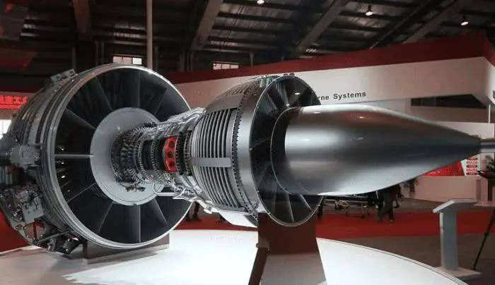
Next.Core structure and operation rationaleThis is the soul of the model.。Large engine models need to focus on the four core components, taking into account “structure integrity” and “principle relevance”: core power components, which are precise core components such as carving gas cylinders, gas tank caps, pistons, warp axes, cam axes, and structural forms, assembly gaps and motor relationships of components, such as piston re-trajectories, rotor logic of axes, cam axes and gas doors, and some functional models that achieve simple motion simulations of core components;Second is the auxiliary system, the cooling system (water tanks, water pipes), the lubrication system (oil pumps, pipelines), the exhaust system (injection tubes, exhaust tubes, turbine boosters), the ignition system (fired plugs, ignition wires), ensuring that the layout, connection of the auxiliary systems are in line with the real engine and that they match the need for power operation.;Three are the control panels, dashboards, valves, sensors, etc. for recapturing engines, the operation buttons, the marking and layout of the monitoring instrument, consistent with the operating manipulation logic.;Fourth, detail markings, including engine models, spare parts numbers, fluid emitter markers, warning markers, etc., each detail must be strictly based on official data to ensure that it is accurate and fit the industrial specifications of large engines.。
Finally.Material selection and process applicationsIt's the core guarantee of model mass and simulation.。Material selection needs to balance "precision, durability, plasticity" with the characteristics of the parts and components of the large engine: core power components such as casks, curves, cam axes, common metal alloy (aluminium alloy, copper alloy), thick ABS plates, small models dominated by high-precision resins (for engraving details), large hands-on models dominated by metal alloys (to increase weight and structural stability), simulation of mechanical strength and metal quality of real engine parts Sensor.;Auxiliary pipes such as water pipes, oil pipelines, often translucent piping, copper piping, distinguishing between different functional piping lines (e.g. red piping, blue piping);The dashboard, the control panel, the high-to-traction panel, the metal sheet, and the wiring printing process to ensure clarity;Seals, buffer parts are often flexible rubber, matching the functional properties of real parts。Processes involving drawings, parts disassembly, material cutting, fine engraving, assembly, polishing, rendering, detail calibration, etc., with colour matching to real large engine colours (mostly silver gray, black, dark blue, metal parts kept bright and warning signs red), as well as the sealing and grinding of parts and components, ensuring seamlessly connected, hairless pricks, with some high-end models designed for disassembly structures (e.g. tank covers open and composted), simulation of engine assembly and overhaul processes, and enhancement of demonstration and interactive features。
II. Questions and answers in the modelling of large engines
Large engine modeling, which is "intensive, complex assembly relationships, difficult to connect to core components, and which highlights the relevance of precision mechanical senses and operating principles", often faces the dual challenge of recalcitrant accuracy of components and the smoothness of core components, with the highest degree of doubt about core power parts recouping and the achievement of interconnectivity functions. The following is a combination of actual scenes, with detailed answers, combining practical and operational, helping to solve pains and improve the quality of models.
Question one: How do we ensure that core power components such as gas cylinders, warp axes and cam axes of large engines, which are assembled in a well-defined relationship and have a fixed track, are refined while ensuring that gaps in assembly are reasonable and that morphological deviations are avoided and that Cardon is fitted?
Answer: The core of the core power parts recapture and assembly is "precision of access to data, precision-processed components, one-to-one calibration" to balance accuracy, assembly difficulty and mobility, highlighting the precision of mechanical features of large engines。First, precision access to core data - before production, access to design drawings, parts assembly manuals for specific large engines through official channels, or scanned modelling of real engine core parts, specifying the size parameters, assembly gaps, motion tracks of parts such as cylinders, curves, cam axes, etc., and drawing 1:1 parts decomposition and assembly maps, indicating the common range of each component (controlled within ±0.05 mm) and avoiding deviations resulting from experience repetition;In the case of complex assembly structures (e.g. collide and bearing, cam axis and gas doors), pre-screening of assembly intervention issues using CAD software modelling assembly simulation processes。Second, precision processing core parts - priority is given to 3D printing + CNC precision processing combinations, with the selection of high-precision metal alloys or resins, 3D printing to ensure that the parts are in a precise form, CNC processing optimizes surface smoothness and size accuracy of the parts, with emphasis on grinding the complementary surface of the parts to ensure that the surface is free of stabbing and smoothness is achieved Indicators;For co-ordinated components such as pistons, cylinders, etc., strict control of co-ordinated gaps to ensure that the pistons are flexible and re-mobilized within the cylinders, without significant relaxation。Finally, calibration assembly on a step-by-step basis — using the method of “striped assembly, piece-by-case calibration” to first assemble core components such as casks, curvature axes, and repeat calibration of assembly gapes and installation angles by calibration of the calibration to ensure that the axis rotates smoothly Yes.;Reassembly components such as cam axes, air doors, calibrate the cam axes and the contour axes, ensuring that the gas door switches are synchronized with the cam axis rotation trajectory;Once the assembly is complete, the core parts are repeatedly tested for motion, the assembly gap is adjusted, the issue of caçaton is cleared, the issue is relaxed, and the parts are sharpened to ensure that the overall assembly is organized and that the actual engine assembly specifications are matched。
Question two: Some large engine models need to be linked to core components (e.g. pistons going back, curves spinning, turbo spinning) and how can they be avoided while ensuring a smooth connection, with misalignment, loss of components, and a balance between connection functions and model durability?
Answer: The core of the core component connection function is "precision design connection structure, rational selection of moving components, repeated debugging optimization", balancing connectivity, structural stability and durability。First, the precise design of the connection structure - based on the power transfer principle of a real large engine, the design of a simple connection structure, such as the use of mini-metallic gears, transfer axes to achieve the alignment of a curve axis with a cam axis, and the use of a condensed pole to connect a piston with a curve axis to ensure that the trajectory of the movement is consistent with the real engine;Convergence structures need to simplify design to avoid the too complex Carton, while leaving a slight activity gap to reduce friction between components。Second, reasonably selected moving components - gears, transfer axes, joins, etc., used for connection, with priority given to high-strength metal materials to ensure robust structures and durable grinding;The gears are selected with fine micro gears, which are precise in range and close, so as to avoid a biting.;The rods are selected with a strong metal thin, which can be slightly shaped to avoid fractures in the connection.;In friction areas such as gears, bearings, etc., a small amount of mini lubricant is painted, wears are reduced and connections are improved. Sex。Finally, repeated calibration optimisation - after completion of the assembly of the associated structures, repeated testing of the state of the actuation, adjusting the length of the gear bites to the length of the pole to ensure that the piston flows back and back, the rotor rotates, the turbine turns in a synchronized fashion, no error, no carton;During the testing process, emphasis is placed on checking the condition of the vulnerable parts, adjusting their assembly position in a timely manner and avoiding damage caused by excessive friction of the components;At the same time, strengthen the fixed parts of the attached structure to ensure that the effect of the connection is maintained after long periods of use, balancing the function of the connection with the durability of the model。
III. Benefits of customizing large engine models
Compared to standardized, generic engine models, customize large engine models, better fit the client's specific engine model, use the scene and core needs, and fully utilize the core values of its presentation, hands-on training, extension, collection, the core benefits of which are focused on three main areas: “adaptability, relevance, utility”, precise solutions to the pain of use of different scenarios, maximization of the value of the model, and technical promotion and talent development of the enabling machine manufacturing industry.
First, it's very well-suited, precise to fit the machine type and the scene needs.。Customized models can be fully tailored to the client-specified large engine types (diesel, gas, turbines, etc.), scale requirements, use scenarios, flexibility in adjusting model structures, parts details, enablers and additional features to achieve “one-on-one fit”。For example, mechanical manufacturing enterprises customize large engine models that allow them to reset their own production, reducing core technological advantages (e.g., large-power tank design, high-efficiency turbine boosters, energy-efficient lubrication systems) for displays at business fairs, client negotiation, product promotion, and helping clients to visualize engine performance advantages and structural characteristics;Schools customised to focus on decompositionability, core component interconnections and assembly details, design of detached tank covers, observational connection structures to facilitate decomposition of observations, simulated assembly and overhaul of students and adapt to practical training needs in mechanical engineering;Customized to focus on the recovery of the overall structure and operating principles, simplifying the details of complex parts, matching the description of the components with a description of the function and power transmission logic, suitable for rapid public knowledge of large engines;Model lovers customise to adjust detail accuracy, select exclusive engine models, add collection identifiers, adapt collection needs and avoid the problem of standardized model “mechanical mismatches, inadequate scenery”。
Second, targeting, highlighting engine characteristics and individual needs。Customization models can focus precisely on the core needs of clients, highlighting the unique characteristics of large engines as “precision and weight, dynamic, structurally organized”, while meeting individualized customization needs。For example, depending on the needs of the client, focus on the restoration of a core technology (e.g., new energy-efficient cylinders, high-efficiency turbovoltage systems, smart monitoring systems), highlighting its own product or technological advantages;Personalized elements can be added, such as enterprise logo, engine model, core technical parameter labels, customised floors (with business concept, technical slogans) for showcasing and showcasing of the enterprise, both to highlight its strength and engine characteristics and to reflect individualized styles.;At the same time, model functions can be adjusted as needed, such as increased core component connection demonstration, light instruction (simulation engine operational status), speech presentation (presentation of operating principles, spare parts function), enhanced demonstration and interaction of models, enhanced presentation, training effects。
Third, there is a multiplicity of practicalities that combine multiple values with higher value for money.。Customize large engine models, not just displays or collections, but with multiple practical values such as displays, hands-on training, promotions, collections and science for “one model multi-purpose”。For mechanical manufacturing enterprises, models can serve as a central vehicle for product promotion and customer negotiation, visualizing the performance advantages and structural characteristics of engines, and helping to increase brand impact and promote performance. Hand it over.;As a technical training tool for staff, to enable them to quickly master parts identification, assembly relationships, overhaul points for engines, shorten the training cycle and upgrade their professional skills。For colleges, models can be used as hands-on teaching aids in mechanical engineering, linking theoretical knowledge and practical operations, helping students quickly understand engine principles, core component functions and improving the quality of hands-on training。For science institutions, models can serve as pictogramal science tools to make abstract mechanical power knowledge, engine operation principles, and help spread knowledge of industrial machinery.。For model lovers, models can serve as collectors of collections, with visual, precision mechanical and collection values, and demonstrate the taste of the collection.。In addition, customized models allow flexibility in the selection of materials, processes and functions based on client budgets, with the option of selecting the base fund (focusing on appearance and structure reduction) or the high end (focusing on disassembly, linked demonstration and detail precision), taking into account practicality and economy.;At the same time, custom model processes and materials can be upgraded as needed, have a longer useful life and can be reused over a long period of time, with value for money well above standardized, generic models。
In summary, large engine modeling is a professional, sophisticated and practical exercise that rationalizes the core concept of dismantling, resolves the key questions in production, selects tailoring options, fully exploits its core advantages of “precision replicating, approximation and quality”, and provides strong support for the demonstration, technical training, institution-based training, science education and collections of mechanical manufacturing enterprises, and contributes to the high-quality development of the mechanical manufacturing industry, technological innovation and talent development.

